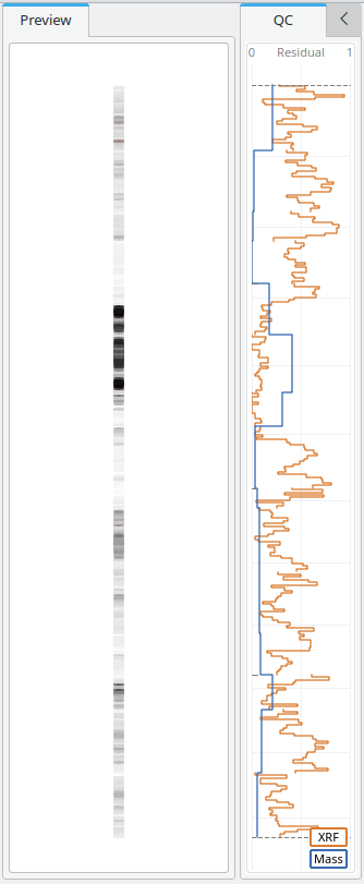
Skip to content

Orexplore Insight 2.3 Released

Orexplore Insight 2.3

2023 is shaping up to be an even more monumentous year for the Insight team here at Orexplore.

Our 2.1 release focused on features for quality control but also brought an entirely new core logging functionality and a tomography clipping tool. The recently released 2.3 version adds new features for particle size distribution and XRF signal plotting, automatically measured joint fracture surfaces and a more streamlined workflow for logging structures.

Orexplore Insight®  is released quarterly and can be downloaded for free here, along with example data. A full description of available features can also be found in the user manual.

New Features

Core Logging

Core logging can now be directly performed within Orexplore Insight. The fully integrated core log view lets the user easily create and adjust log entries, through click-and-drag interactions in the visual representation while leveraging all of the scan data to support their conclusions.

The core log functionality allows the user to flexibly define arbitrary log categories (e.g. ‘Rock type’, ‘Texture’ and ‘Alteration’) and associated log values (e.g. ‘MAS’ and ‘SKARN’, or ‘Fine’ and ‘Coarse’). Results can of course be imported from and exported to CSV format.

Quality Control Plot

The new Quality Control (QC) Plot allows the user to inspect several metrics that measure the performance of the mineralogical fit upon which the GeoCore X10 geochemical analysis is based. Expressed as residuals normalized to a unity range, these metrics summarize how well the fitted mineral mixture agrees with the observables measured by the machine’s load cell (Mass) and x-ray spectrometers (XRF).

Tomography Clipping

The 3D Tomography view, which displays the tomographic data in it’s highest resolution, has now been extended with capability to ‘clip’ the tomographic volume with a freely adjustable plane. The plane divides the volume into a visible and invisible part, which allows to narrow in on further details. The functionality lends itself particularly well to inspection of the core interior, which may otherwise be obstructed and obscured by other features.

Particle size distribution plot

As part of the GeoCore X10 analysis, particles with high x-ray attenuation are extracted and measured from the 3D tomography. Percentiles for the size distribution of these measured particles can now be plotted in Insight. The new plot area can be configured to show different percentiles (p25, p50, p75 and p100), for different particle attenuation thresholds (10, 12, 14, 16, 18 and 20 Al). The down hole resolution of the plotted data can also be configured.


XRF Signal Plot

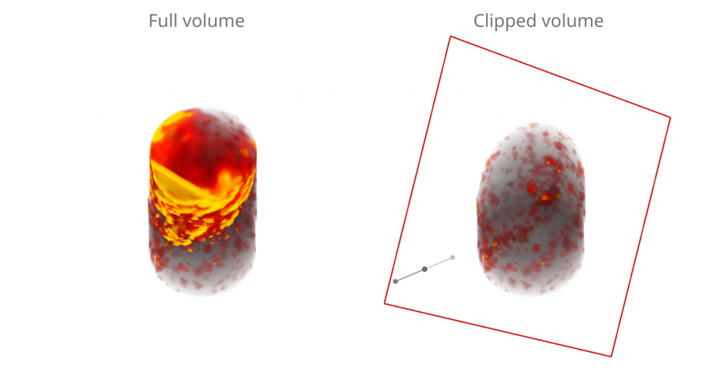
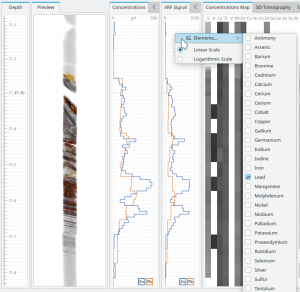
As a complement to the results of the GeoCore X10’s analysis (e.g. element concentrations), Insight now offers the possibility to inspect the strengths of the XRF signals that are part of the input as a rawer form of measurement variable.

The trends of the XRF Signal plot will typically bear a strong resemblance to the corresponding element concentrations, as an increased signal is often linked to an increased concentration. Yet, the mapping from XRF signal to concentration is complex and not always monotonous. The XRF Signal is, therefore, a complement offered for more detailed inspections.

Automatically Measured Joints

Through 3D image analysis of the tomographic reconstruction, the GeoCore X10 identifies each intact piece of drill core. The identification is based on the presence of a partly cylindrical surface, which works both for half and full core. The extent of the identified pieces can be visualised using Show → Core Axes which then shows the core axis segment for each identified piece.

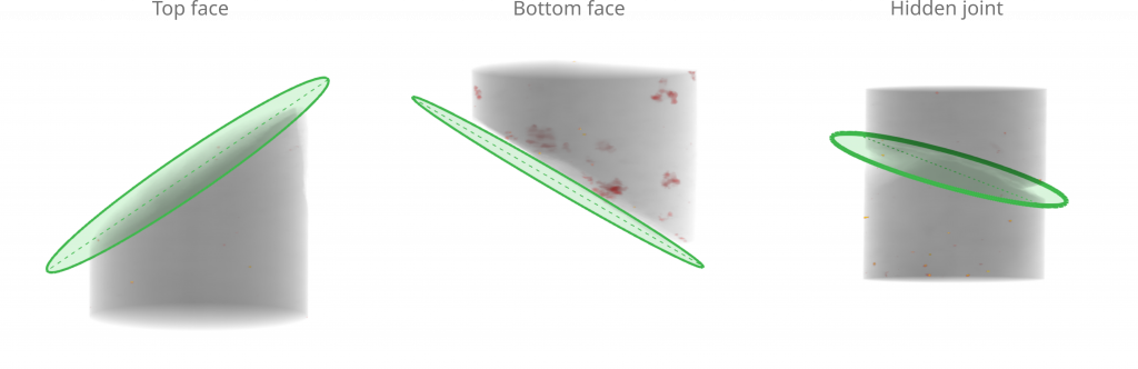
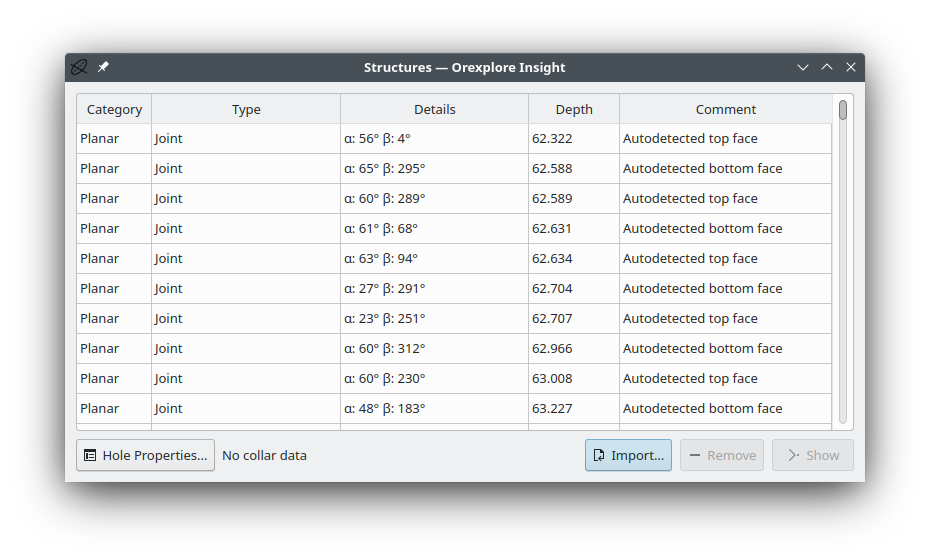
The GeoCore X10 analysis also measured the plane parameters for the joint fracture surfaces on each piece.

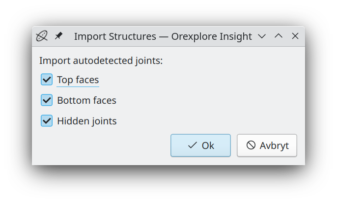
In addition, an ‘Import’ button in the Structures toolbox allows joint fracture surfaces to be imported as automatically detected structures.

Both the top and bottom joint fracture face of each piece can be imported, as well as the harder-to-identify “hidden” joints, between pieces that have been puzzled together well enough to appear like a single fused piece at first glance.

The resulting data set can be used in the calculation of RQD and other geotechnical parameters.

 Interested to hear more about Orexplore and the solutions we can offer with our mineral analysis technology? 

"*" indicates required fields

This field is for validation purposes and should be left unchanged.